Raspberry Pi - Temp/Hum/Press/Air Quality

This is a current in-progress project. Actually it’s half of a project, but I’ve separated it into two parts because some people may wish to do just one part using individual components. This project is based round a Mikroe mikroBUS module called ‘13DOF2 Click’. This small board has two sensor chips:

  • BME680 - This has temperature, humidity, atmospheric pressure and air quality sensors onboard. I’m primarily interested in this for air quality data, but the T/H/P readings may be of use, e.g. to get a better indoor temperature reading then the Davis VP2 console gives because that tends to read high due to internal heating.
  • BMX160 - This is a 9-axis sensor consisting of a 3-axis, low-g accelerometer, a low power 3-axis gyroscope and a 3-axis geomagnetic sensor. It’s intended use is as an orientation sensor, e.g. think they can be used in phones to work out which way up they are and how they’re moving. My initial thoughts for this are to use the accelerometer to make a (probbaly inaccurate) seismometer.

This particular project will cover the BME680 sensors with the BMX160 in another project. The BME680 on the 13DOF2 Click board is described by the manufacturer (Bosch Sensortec) as…

Gas sensor measuring relative humidity, barometric pressure, ambient temperature and gas (VOC).

The BME680 is the first gas sensor that integrates high-linearity and high-accuracy gas, pressure, humidity and temperature sensors. It is especially developed for mobile applications and wearables where size and low power consumption are critical requirements. The BME680 guarantees - depending on the specific operating mode - optimized consumption, long-term stability and high EMC robustness. In order to measure air quality for personal wellbeing the gas sensor within the BME680 can detect a broad range of gases such as volatile organic compounds (VOC).

Possible use cases are:

[ul] [li]Personal air quality tracker[/li] [li]Air quality mapping[/li] [li]Air quality inside cars & public transport[/li] [li]Indicator of too high / low humidity[/li] [li]Air quality & well-being indicator[/li] [li]Weather trends[/li] [/ul]

The project is currently using module parts, which means that in it’s simplest form it’s more or less plug-and-play. That does mean it’s probably more expensive too. However, if you have the skills you can build it from individual parts which is probably going to be cheaper.

Hardware

  • 1*Raspberry Pi - I’m using a 4GB Model 4B but I think this will also work on Model 3 devices with less RAM and possibly Model 2’s too. The GPIO interface on Model 1’s isn’t compatible though. Raspberry Pi’s are available from many sources and I’m treating it as a commodity device so I won’t discuss it too much within the project.
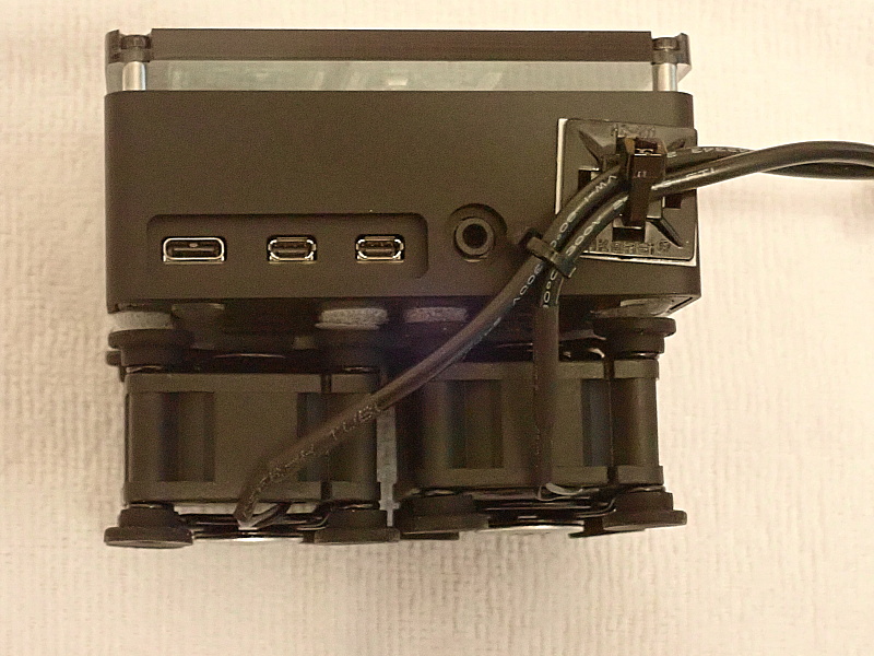
  • 1*Mikroe Pi 3 Click Shield - This is a Pi addon board designed to plug into the 40-pin GPIO connector on a Raspberry Pi. It provides two mikroBUS sockets which allow you to plug a wide variety of ‘click boards’ into the Pi. This is a simple way to add sensors onto a Pi, but be aware that Pi software isn’t available for all of the sensor boards so you may have to write your own/adapt other code. You can buy the Pi 3 Click Shield direct from Mikroe Pi 3 Click Shield in the US, and also some electronics suppliers in other countries, e.g. RS Components or Farnell in the UK. Note that whilst this is called a ‘Pi 3’ shield it is also compatible with the Pi 4 (and I think the Pi 2).
  • 1*Mikroe 13DOF2 Click board - This is a mikroBUS module that plugs into the Pi 3 Click Shield. It has a Bosch Sensortec BME680 and a Bosch Sensortec BMX160 built onto the module with supporting components. You can buy the 13DOF2 Click direct from Mikroe 13DOF2 Click in the US, and also some electronics suppliers in other countries, e.g. Mouser Electronics or Digi-Key Electronics in the UK.

Assembly

  1. Plug the Pi 3 Click Shield onto the 40-pin GPIO connector on the Pi. Follow the instructions for the Click Shield for how to do this. Note: Make sure your Pi is turned off when you do this!
  2. Plug the 13DOF2 Click board into one of the sockets on the Click Shield. It will work in either socket. Mine is plugged into socket 1 because I have another module plugged into socket 2 (see my Lightning Detector project). Ensure the the small GPIO/ADC switch on the Click Shield for the socket you choose is set to GPIO. This should be the default out of the box setting. Note: Make sure your Pi is turned off when you do this!
  3. Turn on your Pi. After the Pi has started to boot up you should see the green LED on the 13DOF3 Click board light up.
  4. That’s it for assembly. The rest is down to software.

Software

As mentioned above, not all Click Boards have software available for them on the Raspberry Pi. This is true in the case of the 13DOF2 Click board. There is some software available to use the BME680 which I’ve checked works on the Raspberry Pi.

There are a number of steps included in the software setup…

  1. Enable I2C on the Raspberry Pi. See https://www.raspberrypi-spy.co.uk/2014/11/enabling-the-i2c-interface-on-the-raspberry-pi/
  2. I’m using Python 3 to access the BME680. If you’re running Raspberry Pi OS (previously called Raspbian OS) then you should have both Python2, Python 3 and pip installed by default. If you’re using another OS or installed a version of the Raspberry Pi OS without Python 3 and pip included please install them using the appropriate method for your OS.
  3. Create a directory “/home/pi/Sensors” for the other software. You can name the directory as you wish, but I’m using Sensors here so that I can refer to it consistently.

The next steps start to cover the Python software. This is still a work in progress for me. For now, I’ve included basic Python code to read data from the BME680 and output it to the terminal window.

  1. [li]Install the BME680 Python support libraries. Enter ‘pip3 install bme680’.
  2. Download the three attached files and place in the Sensors directory. Rename each file from .txt to .py

In the Sensors directory run the ‘temp-press-hum.py’ script using:

python3 temp-press-hum.py

This will display something like the info below. The temperature, pressure and humidity will be read rapidly and output.

pi@IOT-DevPi:~/Sensors $ python3 temp-press-hum.py Display Temperature, Pressure and Humidity

If you don’t need gas readings, then you can read temperature,
pressure and humidity quickly.

Press Ctrl+C to exit

Polling:
30.95 C,1017.71 hPa,30.877 %RH
30.95 C,1017.70 hPa,30.883 %RH
30.96 C,1017.68 hPa,30.891 %RH
30.97 C,1017.70 hPa,30.897 %RH
30.98 C,1017.68 hPa,30.893 %RH
30.99 C,1017.70 hPa,30.898 %RH
31.00 C,1017.68 hPa,30.891 %RH

The temperature (indoor) in my case is high because the module is mounted just above the Pi board so the CPU is heating it. I need to change the construction to keep the sensor at ambient temperature and maybe use a small fan to keep a good airflow past the sensor.

Next run the ‘read-all.py’ script using:

python3 read-all.py

This will display something like the info below. The temperature, pressure, humidity and gas sensor resistance will be read and output along with with various other calibration data from the sensor chip.

pi@IOT-DevPi:~/Sensors $ python3 read-all.py Calibration data: par_gh1: -19 par_gh2: -10936 par_gh3: 18 par_h1: 752 par_h2: 1015 par_h3: 0 par_h4: 45 par_h5: 20 par_h6: 120 par_h7: -100 par_p1: 37097 par_p10: 30 par_p2: -10661 par_p3: 88 par_p4: 7496 par_p5: -93 par_p6: 30 par_p7: 59 par_p8: -4684 par_p9: -1762 par_t1: 26128 par_t2: 26190 par_t3: 3 range_sw_err: 15 res_heat_range: 1 res_heat_val: 45 t_fine: 157742

Initial reading:
gas_index: 0
gas_resistance: 6877278.729487992
heat_stable: False
humidity: 32.409
meas_index: 0
pressure: 1017.73
status: 32
temperature: 30.81

Polling:
30.81 C,1017.71 hPa,32.40 %RH
30.84 C,1017.68 hPa,32.32 %RH,10496.02229501644 Ohms
30.89 C,1017.70 hPa,32.18 %RH,19326.876846977095 Ohms

Next run the ‘indoor-air-quality.py’ script using:

python3 indoor-air-quality.py

This will display something like the info below. Initially, the gas sensor resistance will be output during a 5 minute burn-in period.

pi@IOT-DevPi:~/Sensors $ python3 indoor-air-quality.py Estimate indoor air quality

Runs the sensor for a burn-in period, then uses a
combination of relative humidity and gas resistance
to estimate indoor air quality as a percentage.

Press Ctrl+C to exit

Collecting gas resistance burn-in data for 5 mins

Gas: 15248.344819637847 Ohms
Gas: 28410.649474385635 Ohms
Gas: 37735.37908410996 Ohms
Gas: 49805.362637590595 Ohms
Gas: 59768.48940398531 Ohms

After 5 minutes the display changes to show…

Gas: 297539.15229069436 Ohms Gas: 296524.39794535004 Ohms Gas: 297030.9084362385 Ohms Gas baseline: 297012.87933643296 Ohms, humidity baseline: 40.00 %RH

Gas: 297284.81 Ohms,humidity: 30.22 %RH,air quality: 93.89
Gas: 299847.94 Ohms,humidity: 30.20 %RH,air quality: 93.87
Gas: 298817.40 Ohms,humidity: 30.18 %RH,air quality: 93.86
Gas: 298817.40 Ohms,humidity: 30.17 %RH,air quality: 93.86
Gas: 301407.14 Ohms,humidity: 30.15 %RH,air quality: 93.84
Gas: 298817.40 Ohms,humidity: 30.15 %RH,air quality: 93.84
Gas: 296777.44 Ohms,humidity: 30.17 %RH,air quality: 93.80

The air quality value is calculated by the chip and humdity is part of the calculation. If you prefer it dryer or damper than 40% RH then I believe you can adjust the 40% to your preferred value but I haven’t tried that yet.

The 5 minute burn-in period happens each time you start the script, so the air quality data is best read by a script that runs 24*7 to avoid gaps in the data, or perhaps you could only read air quality data every 5 minutes (or longer)?

The next steps are to write more Python code to use the data, e.g. to output it to screen, send it to another program or create a web page containing the data (or anything else you can think of that would be a useful way to use the data). It may also be necessary to adjust/fine tune some sensor parameters but I haven’t investigate that yet.

I’ve not done any more coding yet, but I’ll post what I do write when I’ve written it. If you understand Python then you probably have enough info to move forward on your own from this point.


temp-press-hum.py.txt (842 Bytes)

indoor-air-quality.py.txt (2.93 KB)

read-all.py.txt (1.63 KB)

Hi Chris,

I thought I’d play around with this sensor.

I’m getting a syntax error on all scripts.

pi@WeatherPi:~/Sensors $ python3 temp-press-hum.py
  File "temp-press-hum.py", line 30
    output = "{0:.2f} C,{1:.2f} hPa,{2:.3f} %RH".format(sensor.data.temperature, sensor.data.pressure, $
                                                                                                       ^
SyntaxError: invalid syntax
pi@WeatherPi:~/Sensors $ python3 read-all.py
  File "read-all.py", line 50
    output = "{0:.2f} C,{1:.2f} hPa,{2:.2f} %RH".format(sensor.data.temperature, sensor.data.pressure, $
                                                                                                       ^
SyntaxError: invalid syntax

pi@WeatherPi:~/Sensors $ python3 indoor-air-quality.py
  File "indoor-air-quality.py", line 78
    else:
       ^
IndentationError: expected an indented block

I think I must have cut and pasted the text at some point and the line has become truncated. In read_all.py and tem-press-hum.py the full line should be…

output = "{0:.2f} C,{1:.2f} hPa,{2:.2f} %RH".format(sensor.data.temperature, sensor.data.pressure, sensor.data.humidity)

In indoor-air-quality.py I’ve managed to get two ‘else:’ on consecutive lines. Just delete one of the two lines.

I’ve updated all three attachments with good versions.

I’m getting further. All 3 py scripts now return this:

pi@WeatherPi:~/Sensors $ python3 temp-press-hum.py
Display Temperature, Pressure and Humidity

If you don't need gas readings, then you can read temperature,
pressure and humidity quickly.

Press Ctrl+C to exit


Traceback (most recent call last):
  File "temp-press-hum.py", line 14, in <module>
    sensor = bme680.BME680()
  File "/home/pi/.local/lib/python3.7/site-packages/bme680/__init__.py", line 25, in __init__
    self.chip_id = self._get_regs(CHIP_ID_ADDR, 1)
  File "/home/pi/.local/lib/python3.7/site-packages/bme680/__init__.py", line 296, in _get_regs
    return self._i2c.read_byte_data(self.i2c_addr, register)
OSError: [Errno 121] Remote I/O error

I’ve got a green light on the sensor board (first socket - left).

Also, I’ve added some fans to the bottom of the Pi. They’re pretty quiet and came with a low-medium-high-off switch. I used two so the Pi would sit on them. They have small rubber cushions on the corners, top and bottom, and I affixed them to the Pi using 1/4" velcro dots. CPU Temperature remains a constant 34C - 93F. I’ll be interested what the board says once it works.


It’s that strange case of programs that used to work no longer working. I don’t know why though :? The fix is easy enough. In each of the three Python programs find the line that says

sensor = bme680.BME680()

and change it to

sensor = bme680.BME680(bme680.I2C_ADDR_SECONDARY)

The sensor is using it’s secondary address so we need to tell the program how to find it. Hopefully you’ll now get some output other than an error.

I’ve updated the attachments to the root message of the thread with the fixed versions.

PS. You’ll have to be careful your Pi doesn’t get frostbite with all that cooling attached!

Well, that’s so cool! The temperature agrees with my thermometer: 30.29. The second floor is warm.

I’m thinking of turning my Pi into a drone so I can maneuver it to different locations. The batteries are an issue :smiley:

I will eventually move on to using sensors like these with Arduino (or similar) devices. They will be much lower power than the Pi and can have comms to send the data back to a central point. Those will be far easier to run from a battery and could easily be attached to a drone.

With the AS3935 sensor project now in a good position I’m coming back to this project. My intention is to make this something like the lightning sensor system, e.g. a monitor service publishing data to MQTT, web page(s) to display the data from MQTT. Config file for setup with an editor. I might spice up the web pages with some graphs and perhaps write the data to a small database for querying/averaging.

I can publish single current readings and/or sets of current+historic readings in JSON format. I can generate averages and highs/lows over periods (especially if there’s database involved). I’ll probably make this up as I go along, but if you’ve got any suggestions about what the system might look like or features it might have now is the time to suggest them!

That would be awesome!

I’ve started digging into this and it looks like I’ll need a combination of C/C++ and Python. The ‘best’ BME680 library is only available in C as a closed source binary. So I’ll need to put on my C hat. That also means that I won’t be able to publish full source code for this project. I’ll publish as much as I can but I’ll need to look carefully at the licensing conditions for the libraries to see what I’m allowed to publish.

Say I want an iot of skycamera, lightening detector, air quality can I run all this on one PI4? Seems to me you should be able to run a loop, poll this, that, other, repeate. Probably need an output after each item. Then how do you use the output, a .php page? I notice there is an audio jack on the camera board, I assume there are microphones/transducers that plug into them, could you use it for audio for a skycam, especialy if there was a storm.

As for the seismic dectector I don’t see why it would not be relativly sensitive if mounted on some sold thing in the ground. Except on Thursday morning when the garbage truck rumbles down the alley. Unless there just isn’t the resolution to the sensor it’s self.

Is there a good R. Pi book to read?

I suspect that they could all run together on a Pi4. They’re not all polling loop capable though. Lightning is interrupt driven so polling may lose data if the Pi is busy doing other things. I’m not sure how the Pi handles the camera, i.e. does it process the data all the time or only read the camera when you ask for an image.

As for the seismic dectector I don't see why it would not be relativly sensitive if mounted on some sold thing in the ground. Except on Thursday morning when the garbage truck rumbles down the alley. Unless there just isn't the resolution to the sensor it's self.

The sensor has a wide sensitivity range so I’m hopeful that it will be able to detect movement. The biggest problem I see is that it should really be bolted down to a big immovable object and I’m not sure how to achieve that with the sensor board in the configuration it’s in, i.e. mounted onto the Pi. I’ll probably develop the software using the sensor as is but then look for a standalone sensor that can be put on the end of a wire allowing it to be separated from the Pi and bolted down somewhere. I might try to get the Pi out into the garage and then bolt the sensor to the floor slab. That’s a big solid piece of concrete so less prone to wobbles! My car won’t fit in the garage so that’s not going to cause a problem!

Is there a good R. Pi book to read?

Sorry, I can’t help with that. I’ve used Pi’s for years, I had a Pi 1 back in the day, so now I just learn bits that I need online.

I’ve been trying to make progress with the air quality sensor but it’s tricky because the Bosch code is only provided as a pre-compiled library. I’m having problems getting that to link to a program compiled to work with it. I’m still digging my way through suggestions so I’m sure I’ll get there in the end, it’s just a slow process. When I do get it working it should be fairly easy to get data from the sensor and make it available on a web page.

Patiently waiting :smiley:

I’ve made some progress! I’ve managed to compile and link a test program that uses the Bosch library to interrogate the sensor chip…

Time 1600953764670310000, IAQ 47.036461, IAQ_Accuracy 1, Temperature 28.355307 Time 1600953767669846000, IAQ 46.700653, IAQ_Accuracy 1, Temperature 28.435295 Time 1600953770669560000, IAQ 46.399063, IAQ_Accuracy 1, Temperature 28.465300 Time 1600953773669473000, IAQ 45.585526, IAQ_Accuracy 1, Temperature 28.355307 Time 1600953776669511000, IAQ 46.162102, IAQ_Accuracy 1, Temperature 28.305309 Time 1600953779669046000, IAQ 45.054573, IAQ_Accuracy 1, Temperature 28.255295 Time 1600953782668969000, IAQ 46.468758, IAQ_Accuracy 1, Temperature 28.385305 Time 1600953785668451000, IAQ 45.062180, IAQ_Accuracy 1, Temperature 28.355293 Time 1600953788667918000, IAQ 43.991402, IAQ_Accuracy 1, Temperature 28.325291 Time 1600953791667824000, IAQ 45.084984, IAQ_Accuracy 1, Temperature 28.285305

As you can see my air quality is good :slight_smile:

Now that I have the program compiling and linking I can move on to make it output the data to one or more MQTT topics.

There’s more data in the sensor than I previously showed. I’ve modified the program to output more (see below). The listed values are:

Epoch time, Air Quality Index (0-500), AQI accuracy, Adjusted Temp (C), Raw Temp, Adjusted Humidity (%), Raw Humidity, Pressure (hPa), Gas sensor resistance (ohms), Static AQI (not sure what this is), CO2 Equivalent, Breath Volatile Organic Components (VOC) Equivalent. I haven’t looked what the units are for CO2 and VOC.

1600972988, AQI 95.93, AQI Acc 1, T=28.1 Raw T=29.8 H=39.4 Raw H=35.6 P=993.81 Gas=169416.0 SAQI=55.98 CO2=623.94 VOC= 0.80 1600972991, AQI 96.31, AQI Acc 1, T=28.1 Raw T=29.9 H=39.5 Raw H=35.8 P=993.77 Gas=169934.0 SAQI=56.15 CO2=624.61 VOC= 0.80 1600972994, AQI 93.31, AQI Acc 1, T=28.1 Raw T=29.9 H=39.3 Raw H=35.5 P=993.79 Gas=171506.0 SAQI=54.84 CO2=619.36 VOC= 0.79 1600972997, AQI 89.24, AQI Acc 1, T=28.1 Raw T=29.8 H=39.1 Raw H=35.3 P=993.83 Gas=172570.0 SAQI=53.06 CO2=612.25 VOC= 0.76 1600973000, AQI 86.32, AQI Acc 1, T=28.0 Raw T=29.8 H=38.9 Raw H=35.1 P=993.81 Gas=172748.0 SAQI=51.78 CO2=607.14 VOC= 0.75 1600973003, AQI 81.96, AQI Acc 1, T=28.0 Raw T=29.8 H=38.8 Raw H=35.0 P=993.79 Gas=174009.0 SAQI=49.88 CO2=599.53 VOC= 0.73 1600973006, AQI 79.54, AQI Acc 1, T=28.0 Raw T=29.8 H=38.7 Raw H=34.9 P=993.81 Gas=173828.0 SAQI=48.82 CO2=595.30 VOC= 0.72 1600973009, AQI 75.92, AQI Acc 1, T=27.9 Raw T=29.7 H=38.8 Raw H=34.9 P=993.79 Gas=174921.0 SAQI=47.24 CO2=588.97 VOC= 0.70 1600973012, AQI 74.76, AQI Acc 1, T=27.9 Raw T=29.7 H=38.8 Raw H=34.8 P=993.79 Gas=174373.0 SAQI=46.74 CO2=586.94 VOC= 0.69 1600973015, AQI 70.74, AQI Acc 1, T=27.9 Raw T=29.7 H=38.8 Raw H=34.9 P=993.81 Gas=176028.0 SAQI=44.98 CO2=579.91 VOC= 0.68

The adjusted values are an attempt by the sensor to adjust for the heat generated by the hardware (RPi) associated with the sensor. I’m sure this has configuration values that can be tweaked. The sensor seems quite sensitive. I can make the air quality values change just by gently blowing in the general direction of the sensor from about 50cm away. I’m not sure whether the higher VOC level at the start was due to a mango being peeled nearby…I don’t know of any other raised volatile organics in the air at that time!

I’ve made some more progress. I now have a C program which can read the sensor and output the data to an MQTT topic. The program isn’t configurable at this stage, so no way to write to another MQTT broker and I need to do a few more tweaks to it to make it more ‘production ready’. Once this step is over things should move faster because I can switch over to Python to read the MQTT data stream and process it further.

Sounds like it’s coming along nicely!

You might want to try some lemons in a blender to see how the readings stack up against a mango.