This is a current in-progress project. I’m using an ams AS3935 lightning detection sensor IC with a Raspberry Pi to detect lightning within approx 40km. To quote from the manufacturer about the AS3935…
AS3935 Franklin Lightning Sensorâ„¢ IC is a programmable fully integrated lightning sensor that detects the presence and approach of potentially hazardous lightning activity in the vicinity and provides an estimation on the distance to the head of the storm. The embedded lightning algorithm checks the incoming signal pattern to reject the potential man-made disturbers. The AS3935 can also provide information on the noise level and inform the external unit (e.g. microcontroller) in case of high noise conditions, with the noise floor generator and noise floor evaluation blocks.
[ul] [li]Lightning sensor warns of lightning storm activity within a radius of 40km[/li] [li]Distance estimation to the head of the storm down to 1km in 14 steps[/li] [li]Detects both cloud-to-ground and intra-cloud (cloud-to-cloud) flashes[/li] [li]Embedded man-made disturber rejection algorithm[/li] [li]Programmable detection levels enable threshold setting for optimal controls[/li] [li]SPI and I²C interface is used for control and register reading[/li] [li]Antenna Tuning to compensate variations of the external components[/li] [li]Supply voltage range: 2.4V to 5.5V[/li] [li]Power-down, listening, and active mode[/li] [li]Package: 16LD MLPQ (4x4mm)[/li] [/ul]
The project is currently using module parts, which means that in it’s simplest form it’s more or less plug-and-play. That does mean it’s probably more expensive too. However, if you have the skills you can build it from indivudual parts which is probably going to be cheaper.
Hardware
- 1*Raspberry Pi - I’m using a 4GB Model 4B but I think this will also work on Model 3 devices with less RAM and possibly Model 2’s too. The GPIO interface on Model 1’s isn’t compatible though. Raspberry Pi’s are available from many sources and I’m treating it as a commodity device so I won’t discuss it too much within the project.
- 1*Mikroe Pi 3 Click Shield - This is a Pi addon board designed to plug into the 40-pin GPIO connector on a Raspberry Pi. It provides two mikroBUS sockets which allow you to plug a wide variety of ‘click boards’ into the Pi. This is a simple way to add sensors onto a Pi, but be aware that Pi software isn’t available for all of the sensor boards so you may have to write your own/adapt other code. You can buy the Pi 3 Click Shield direct from Mikroe Pi 3 Click Shield in the US, and also some electronics suppliers in other countries, e.g. RS Components or Farnell in the UK. Note that whilst this is called a ‘Pi 3’ shield it is also compatible with the Pi 4 (and I think the Pi 2).
- 1*Mikroe Thunder Click board - This is a mikroBUS module that plugs into the Pi 3 Click Shield. It has an AS3935 lightning detector chip and a MA5532 coil antenna built onto the module with supporting components. You can buy the Thunder Click direct from Mikroe Thunder Click in the US, and also some electronics suppliers in other countries, e.g. RS Components or Farnell in the UK.
Assembly
- Plug the Pi 3 Click Shield onto the 40-pin GPIO connector on the Pi. Follow the instructions for the Click Shield for how to do this. Note: Make sure your Pi is turned off when you do this!
- Plug the Thunder Click board into one of the sockets on the Click Shield. It will work in either socket. Mine is plugged into socket 2 because I have another module plugged into socket 1 (see another project to be documented later on). Ensure the the small GPIO/ADC switch on the Click Shield for the socket you choose is set to GPIO. This should be the default out of the box setting. Note: Make sure your Pi is turned off when you do this!
- Turn on your Pi. After the Pi has started to boot up you should see the green LED on the Thunder Click board light up.
- That’s it for assembly. The rest is down to software.
Software
As mentioned above, not all Click Boards have software available for them on the Raspberry Pi. This is true in the case of the Thunder Click board. There is some software available to use the AS3935 but much of this is for using the chip on its I2C interface but the Thunder Click is configured to use SPI (Serial Peripheral Interface) which meant that I had re-work some existing code to make it work.
There are a number of steps included in the software setup…
- Enable SPI on the Raspberry Pi. See https://www.raspberrypi-spy.co.uk/2014/08/enabling-the-spi-interface-on-the-raspberry-pi/
- I’m using Python 3 to access the AS3935. You also need to use ‘pip’. If you’re running Raspberry Pi OS (previously called Raspbian OS) then you should have both Python2, Python 3 and pip installed by default. If you’re using another OS or installed a version of the Raspberry Pi OS without Python 3/pip included please install them using the appropriate method for your OS.
- Install Python SpiDev. This is a small software module that can be used from Python to access SPI connected devices. At the Pi OS prompt use ‘pip3 install spidev’ to install this module.
- Create a directory “/home/pi/Sensors” for the other software. You can name the directory as you wish, but I’m using Sensors here so that I can refer to it consistently.
- Put a copy of the attached C source code (as3935_spidev_test.txt) into the Sensors directory and rename it to as3935_spidev_test.c
- Compile the C source code using 'gcc -o as3935_spidev_test as3935_spidev_test.c
[li]Test the Thunder Click board by running the test program. The program defaults to the Thunder Click being plugged into socket 2 of the Pi 3 Click Shield. If your Thunder Click is also plugged into socket 2 run the program using ‘as3935_spidev_test -H 0x40,0,0,0,0,0,0,0,0,0’. If your Thunder Click is plugged into socket 1 of the Click Shield run the program using ‘as3935_spidev_test -H -D /dev/spidev0.0 0x40,0,0,0,0,0,0,0,0,0’. You should get two lines of output if things are working correctly which look something like this…
40 00 00 00 00 00 00 00 00 00
00 24 32 C2 20 00 00 00 3F 0F
The numbers on the second line may vary a little depending on the current state of the AS3935. If you get an output like this then your installation is probably OK.[/li]
The next steps start to cover the Python software. This is still a work in progress for me. For now, I’ve included the some AS3935 library routines converted from I2C to SPI connection and a simple Python3 program to get some output and start monitoring for lightning.
- Download the attached file ‘RPi_AS3935_SPI.txt’ and put it in the Sensors directory. Rename the file to ‘RPi_AS3935_SPI.py’
- Download the attached file ‘thunder_interrupt.txt’ and put it in the Sensors directory. Rename the file to ‘thunder_interrupt.py’
[li]If your Thunder Click is plugged into socket 1 of the Click Shield you must modify thunder_interrupt.py as follows. Edit the file, e.g. using ‘nano’, and find the line containing 'as3935 = RPi_AS3935(bus=0, address=1, mode=0b10, speed=400000)
’ (should be line 11) and change ‘address=1’ to ‘address=0’. Save the modified file. [/li]
[li]In the Sensors directory run the thunder_interrupt.py script using ‘python3 thunder_interrupt.py’. You should see some output something like…
Waiting for lightning - or at least something that looks like it
Noise level too high - adjusting
You may see no noise level entries, or multiple of them depending on how electrically noisy your location is.
[/li]
thunder_interrupt.py configures the AS3935 for indoor use, sets the noise floor and calibrates the frequency of operation. These are unlikely to be optimal settings for all use. The code probably isn’t written well, or optimised, but it’s for demo purposes only to check that you can access the Thunder Click from Python.
After the setup, it adds an interrupt handler. Simply put, when the AS3935 wants to signal that something has happened, e.g. lightning is detected, or the noise level has changed, etc, it interrupts the Raspberry Pi (using GPIO 26) which causes the ‘handle_interrupt’ code to be executed. This code checks the AS3935 registers to find out what has been signalled and displays it on screen…then goes back to waiting for the next interrupt.
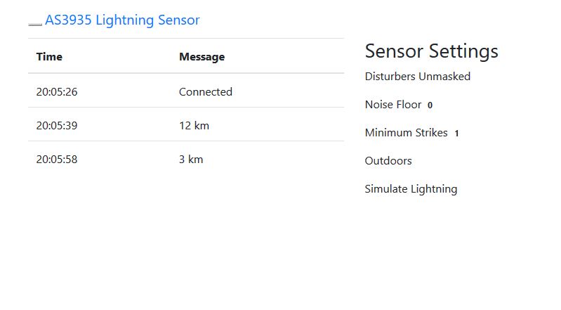
The next steps are to write more Python code to use the data, e.g. to output it to screen, send it to another program or create a web page containing the data (or anything else you can think of that would be a useful way to use the data). I’ve not done any more coding yet, but I’ll post what I do write when I’ve written it. If you understand Python then you can probably continue from this point to do your own thing.
as3935_spidev_test.txt (8.08 KB)
RPi_AS3935_SPI.txt (7.49 KB)
thunder_interrupt.txt (1.18 KB)