Raspberry Pi Lightning Detector - v1 and v2

Weird :? The copy of the file on my Pi doesn’t have the duplicated function. I wonder where that came from!

Anyway, it’s not too relevant because that program isn’t required by version 2. You can still use it to test your AS3935 as you’ve got that far through the install though.

I got my first AS3935 from Playingwithfusion and installed it with the RPi. I got the code from some git repository and modified it to my needs. It was installed under in the yard under the wooden roof. I live in a mountainous region so didn’t expect much but it reads the strikes as far as 10-20 km away. It usually picks up the strikes in the direction of the valley but less successfully over the mountains (1000-2000 m).
I sourced another detector from same vendor (it’s plug and play) but hooked it to an Arduino Nano. Arduino is connected to a RPi which only records what comes over the USB port. I like this setup more since it is more flexible to install (longer cable, e.g. 2 m). This detector is installed in a flat region with mountains on the north side. It is extremely sensitive (set to outdoor!) and starts picking up strikes as far as 60-100 km away.
Third detector is hooked to an Arduino and works OK. For all detectors I use the capacitor’s value written on the detector’s package.


Detector #1 started reporting false strikes after ~2 years in operation. After investigation I found out it had issues with I2C communication. Long story short. I have it now on the Arduino with SPI. It lives, reports the disturber and noise when I put it close to the laptop’s hard drive but is almost dough when the storm approaches. Tried many things, but no success. It is now set to outdoor with disturber mask disabled.

I read few posts on the wxforum but not really thoroughly. I also studied the Boltek’s user manual for their LD-250 where they suggest that the antenna must not be installed in proximity of a metallic object and must not be grounded. I also follow the WeatherFlow’s suggestions where they say the detection performance depends on the detector’s orientation.

I now wonder about other people’s experience with AS3935 and any modification that can be done to optimize the detection performance. I obviously had luck with detector #2 but not with #1.
Specifically, I’m interested how/where to install (e.g. wooden pole?), how to rotate the detector, set the noise, spike rejection, etc.
Is it possible to connect an external antenna?

All this interests me since I’m curious if Boltek’s system would work (much) better in my mountainous location. The price difference between the two systems is enormous.

Finished, all working Chris, :smiley:

This is version 2 of the AS3935 project. I’m a lot happier with the way this version behaves.

It uses some different software components than version 1. You shouldn’t need to rebuild your Pi if you’ve started setting up with version 1. The v1 components won’t interfere with the v2 components, although I would advise that you rename your existing ‘Sensors’ directory and start afresh with a new, empty directory.

This is a current in-progress project. I’m using an ams AS3935 lightning detection sensor IC with a Raspberry Pi to detect lightning strikes within approx 40km. To quote from the manufacturer about the AS3935…

AS3935 Franklin Lightning Sensorâ„¢ IC is a programmable fully integrated lightning sensor that detects the presence and approach of potentially hazardous lightning activity in the vicinity and provides an estimation on the distance to the head of the storm. The embedded lightning algorithm checks the incoming signal pattern to reject the potential man-made disturbers. The AS3935 can also provide information on the noise level and inform the external unit (e.g. microcontroller) in case of high noise conditions, with the noise floor generator and noise floor evaluation blocks.
[ul] [li]Lightning sensor warns of lightning storm activity within a radius of 40km[/li] [li]Distance estimation to the head of the storm down to 1km in 14 steps[/li] [li]Detects both cloud-to-ground and intra-cloud (cloud-to-cloud) flashes[/li] [li]Embedded man-made disturber rejection algorithm[/li] [li]Programmable detection levels enable threshold setting for optimal controls[/li] [li]SPI and I²C interface is used for control and register reading[/li] [li]Antenna Tuning to compensate variations of the external components[/li] [li]Supply voltage range: 2.4V to 5.5V[/li] [li]Power-down, listening, and active mode[/li] [li]Package: 16LD MLPQ (4x4mm)[/li] [/ul]

The project is currently using module parts, which means that in it’s simplest form it’s more or less plug-and-play. That does mean it’s probably more expensive too. However, if you have the skills you can build it from individual parts which should be cheaper. I have received a non-Mikroe board that doesn’t need the Pi 3 Click Shield and will test it soon. If you can solder (7 wires) to a small-ish board then you should be able to save some money by using the second approach. I’ll document it when I’ve tested it. Here’s what you need for the project as it stands…

Hardware

  • 1*Raspberry Pi - I’m using a 4GB Model 4B, but I think this should also work on Model 3 devices with less RAM and possibly Model 2’s too. The GPIO interface on Model 1’s isn’t compatible though. Raspberry Pi’s are available from many sources and I’m treating it as a commodity device so I won’t discuss it too much within the project. My Pi has the ‘Full’ version of Raspberry Pi OS installed using the Pi Imager tool which is downloadable from the Raspberry Pi site. These instructions assume that your Pi is already built, with the OS installed, is set up to work on your network, that you’re able to log into it and that it’s updated with the latest Pi OS and standard software.
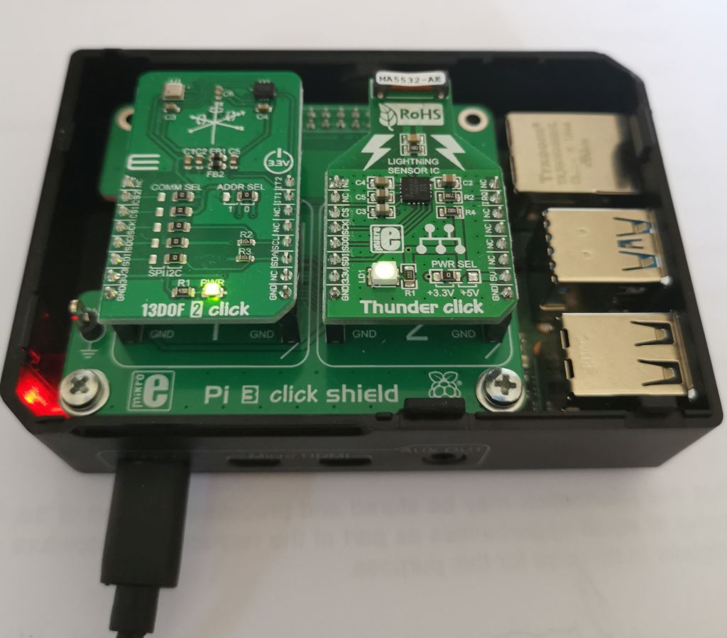
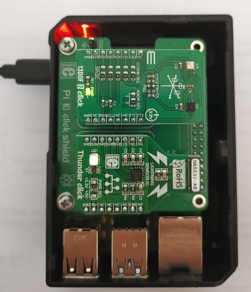
  • 1*Mikroe Pi 3 Click Shield - This is an addon board designed to plug into the 40-pin GPIO connector on a Raspberry Pi. It provides two mikroBUS sockets which allow you to plug a wide variety of ‘click boards’ into the Pi. This is a simple way to add sensors onto a Pi, but be aware that Pi software isn’t available for all of the sensor boards so you may have to write your own/adapt other code. You can buy the Pi 3 Click Shield direct from Mikroe Pi 3 Click Shield in the US, and also some electronics suppliers in other countries, e.g. RS Components or Farnell in the UK. Note that whilst this is called a ‘Pi 3’ shield it is also compatible with the Pi 4 (and I think the Pi 2).
  • 1*Mikroe Thunder Click board - This is a mikroBUS module that plugs into the Pi 3 Click Shield. It has an AS3935 lightning detector chip and a MA5532 coil antenna built onto the module with supporting components. You can buy the Thunder Click direct from Mikroe Thunder Click in the US, and also some electronics suppliers in other countries, e.g. RS Components or Farnell in the UK.

Assembly

  1. Plug the Pi 3 Click Shield onto the 40-pin GPIO connector on the Pi. Follow the Click Shield instructions for how to do this. Note: Make sure your Pi is turned off when you do this!
  2. Plug the Thunder Click board into one of the sockets on the Click Shield. It will work in either socket. Mine is plugged into socket 2 because I have another module plugged into socket 1 (see another project to be documented later on). Ensure the the small GPIO/ADC switch on the Click Shield for the socket you choose is set to GPIO. This should be the default out of the box setting. Note: Make sure your Pi is turned off when you do this!
  3. Turn on your Pi. After the Pi has started to boot up you should see the green LED on the Thunder Click board light up.
  4. That’s it for assembly. The rest is down to software.

Software

As mentioned above, not all Click Boards have Raspberry Pi software available for them. This is true for the Thunder Click board. There is some software available from other sources to use an AS3935 on a Pi but much of this is for using the chip on its I2C interface. The Thunder Click is configured to use the SPI (Serial Peripheral Interface) bus which meant that I’ve had to re-work some existing code to make it work.

There are a number of steps included in the software setup…

  1. Enable the SPI bus on the Raspberry Pi. See https://www.raspberrypi-spy.co.uk/2014/08/enabling-the-spi-interface-on-the-raspberry-pi/
  2. I’m using Python 3 to access the AS3935. You also need to use ‘pip’. If you’re running Raspberry Pi OS (previously called Raspbian OS) then you should have both Python 3 and pip installed by default. If you’re using another OS or installed a version of the Raspberry Pi OS without Python 3/pip included please install them using the appropriate method for your OS.
  3. Create a directory “/home/pi/Sensors” for the AS3935 software. You can name the directory as you wish, but I’m using Sensors here so that I can refer to it consistently.
  4. Install the pigpio library. At the time of writing there are different ways to do this depending on whether you’re using a Raspberry Pi 4 or not. The ‘long’ method is appropriate for any Raspberry Pi but must be used for the Pi 4. A shorter method can be used for a Raspberry Pi 3 (or 2). The Pi 4 requires version 76 of the library and that’s not yet available in the Python (pip) library which is why the longer method must be used to install the latest version of the library.
    [li]Use this short method to install the pigpio library onto a Raspberry Pi 3 (or 2). Type these commands into a Pi terminal session:
    sudo apt-get update
    sudo apt-get install pigpio python-pigpio python3-pigpio

    [/li]
    [li]Use this longer method to install the pigpio library onto a Raspberry Pi 4. Type the following commands into a Pi terminal session:
    sudo apt install python-setuptools python3-setuptools
    cd Sensors
    wget https://github.com/joan2937/pigpio/archive/master.zip
    unzip master.zip
    cd pigpio-master
    make
    sudo make install

    If you want to test that the installation works properly you can use the following commands. This step is optional but may be required if you have problems getting pigpio working. The tests will probably take 5-10 minutes to complete.
    sudo ./x_pigpio # check C I/F
    sudo pigpiod # start daemon
    ./x_pigpiod_if2 # check C I/F to daemon
    ./x_pigpio.py # check Python I/F to daemon
    ./x_pigs # check pigs I/F to daemon
    ./x_pipe # check pipe I/F to daemon

    The results of the tests should be fairly obvious. I get the error ‘ERROR: No more CBs for waveform’ when running the x_pigs test. This doesn’t appear to affect what we need to use the library for. At the end of the installation/test type ‘cd …’ to return to the ‘Sensors’ directory.
    [/li]

The next steps start to cover the Python software. This is still a work in progress. For now, I’ve converted an AS3935 library written for an I2C connection to use SPI. There are also Python3 programs to test that you can connect to the AS3935, find the best calibration setting and do some simple monitoring of the AS3935 to report lightning to the console.

  1. Download the attached ‘AS3935_v2.zip’ file, upload it to your Pi and unzip it into the Sensors directory.
  2. If your Thunder Click is plugged into socket 1 of the Click Shield you must modify as3935_pigpio_test.py, calibrate_pig.py and thunder_interrupt.py as follows. Edit each file, e.g. using ‘nano’, and find the line containing ‘as3935 = RPi_AS3935(bus=0, address=1, mode=0b10, speed=400000)’. Change ‘address=1’ to ‘address=0’. Save the modified file.
    [li]Run as3935_pigpio_test.py by typing
    python3 as3935_pigpio_test.py

    You should get some output like:
    pi@raspberrypi:~/Sensors $ python3 as3935_pigpio_test.py
    Test starting
    Register 0x00 is 0x24
    Register 0x01 is 0x02
    Register 0x02 is 0xC2
    Register 0x03 is 0xC0
    Register 0x04 is 0x00
    Register 0x05 is 0x00
    Register 0x06 is 0x00
    Register 0x07 is 0x3F
    Register 0x08 is 0x0A
    Test complete

    The displayed values may vary depending on the exact initial state of your AS3935. If your hardware isn’t set up correctly then you will either see an error or possibly all 0x00 or 0xFF values displayed. Getting similar numbers to those above is a good sign that everything is working properly.
    [/li]
    [li]Next you need to calibrate the AS3935 to find the correct antenna tuning capacitance for lightning detection. The antenna needs to be tuned to 500kHz +/- 3.25% and part of register 0x08 is used to set the capacitance. To find the best capacitance to use for your AS3935 module run calibrate_pig.py by typing:
    python3 calibrate_pig.py

    The calibration run will take about 16 seconds (or longer if you’ve changed the ‘increment_time’ variable). At the end of the run you should get some output like this…
    pi@raspberrypi:~/Sensors $ python3 calibrate_pig.py
    Starting calibration run - Please wait approximately 16 seconds
    Success!
    Tuning Capacitor setting - 0x0A - 80 pF
    Percent variance = 0.04 %

    The important value is the ‘0x0A’ (or equivalent number for your module). Make a note of the value because you’ll need to edit it into other programs or config files. If you forget it you can always re-run the calibrate_pig.py program to get it again.

    It’s possible to get a failure reported by the calibration run. This happens when none of the tuning capacitor values can tune the antenna within 3.25% of 500kHz. This possibly indicates faulty hardware but there can be other reasons for this, e.g. having the wrong configuration values defined in the calibration program.
    [/li]
    [li]Edit the thunder_interrupt.py program, e.g. using ‘nano’, to set the calibrated capacitance value for your module. Find the line ‘as3935.calibrate(tun_cap=0x0A)’ and change the value ‘0x0A’ to your own calibration value from the calibration run (see above).
    [/li]
    [li]
    Run the thunder_interrupt.py script by typing:
    python3 thunder_interrupt.py

    You should see some output something like this displayed…
    pi@raspberrypi:~/Sensors $ python3 thunder_interrupt2.py
    Configured to run with antenna tuning capacitance of 80 pF

    Waiting for lightning…
    Press Ctrl+C to exit.

    Noise level too high. Raising noise floor.
    Noise level too high. Raising noise floor.

    You may see no noise level entries, or multiple of them depending on how electrically noisy your location is. You might also see disturbers reported. These are other strong local signals that don’t fit the pattern for lightning. When this software sees the first disturber it disables disturbers from being reported for the duration of the run. If you’re lucky and there’s local lightning you’ll also see lightning strikes, with their estimated distance and energy, reported.
    [/li]

thunder_interrupt.py configures the AS3935 for indoor use, sets the noise floor and sets the antenna tuning capacitance. These probably aren’t optimal settings for all use but you can change the settings if you like. The code probably isn’t written well, or optimised, but it’s for demo purposes only to check that you can access the Thunder Click from Python and that it detects a high noise floor, disturbers and, when there is some, detects lightning strikes.

After the config is done, it adds an interrupt handler function. Simply put, when the AS3935 wants to signal that something has happened, e.g. lightning has been detected, or the noise level has changed, etc, it interrupts the Raspberry Pi (using GPIO 26) which causes the ‘handle_interrupt’ code to be executed. This code looks at register 0x03 of the AS3935 to find out the reason for the interrupt and then displays it on screen. After the interrupt has been handled it goes back to waiting for the next interrupt.

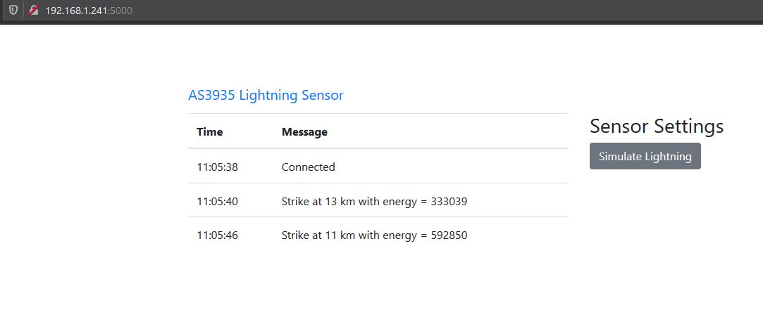
This is the end of the first stage. If you’ve completed all these steps then you’ve got a functional AS3935 that can be accessed by Python. I’ve got a basic web server nearly ready to go that will display the data in a nicer way and will also allow a ‘nowcast.txt’ file to be accessed via the web server. This file should allow Weather Display to read the lightning data generated by the AS3935. I’ll post this code when it’s ready and documented.

Note: This configuration isn’t production ready yet. For example, you’ll need to manually restart pigpiod and the python software if you reboot the Pi. I’ll work on those after I get the first version of the web server published.


AS3936_v2.zip (7.9 KB)

I’m still in the early days of using an AS3935, so early in fact that there haven’t been any thunderstorms in the area since I had a workable system. I did read somewhere that the I2C interface on the AS3935 has problems and you really need to use SPI to effectively access the chip so that confirms what you’ve found.

I’ve not yet thought much about how to mount the sensor. It’s been sitting next to my laptop to allow me to develop the AS3935 code on the Pi, although thinking about it I could really put it anywhere in the house because it’s WiFi connected. My only thought so far is to put it in my loft which is the most remote and least electrically noisy part of the house (that has a power connection). My garden isn’t huge anyway, so pretty much anywhere I could mount it would probably suffer from much the same amount of noise as in the loft (and I’d have to figure out how to get power to it).

I’d be surprised if the sensor was directional. The MA5532 antenna is tiny for the frequency it’s detecting and I suspect it really only works due to the massive amount of RF energy generated by a lightning strike. Even a small antenna is bound to see some of that energy if the strike is close enough. The closest I can come to the antenna equivalence is a longwave AM radio. They often have coils wound on a graphite core for use at those frequencies. They were directional to an extent, but the coil was much bigger and the graphite core would have played a big part in the directionality too.

Having said that, I don’t think adding a bigger/external antenna onto the chip would be a good idea. I suspect that a bigger antenna would at best overload the front-end of the chip, effectively making it seem far noisier and giving more false positives, and in the worst case actually fry the chip, particularly with a close lightning strike. The chip is designed for small amounts of RF voltage/current from a small antenna, not large voltages/currents!

Finally, I’ve not see anything in any documentation so far to suggest that the sensor must be mounted away from metal. Metal can have an effect on RF, but as this isn’t intended to be directional it probably wouldn’t have a significant effect. The Boltek antenna is clearly directional because that’s a feature of the system and a big chunk of metal near that antenna could easily change the electromagnetic pattern near the antenna and mess up the direction finding capability.

Hi Chris,

I’ve ordered the boards and the Raspberry Pi you recommended came via Amazon today. There was an Alexa notification that the Raspberry Pi would arrive today that my wife intercepted. She was wondering why I ordered a rhubarb pie and I corrected her that it’s a Raspberry Pi. She looked puzzled.

I’m new to the Pi world. I have a 16" flat panel monitor that should work with it and I ordered a USB keyboard that was advertised as being Pi compatible.

I downloaded your files. I haven’t looked to see what’s on the SD card that came with the unit. I take it that Python should be on it?

Do I copy the files to the card from my PC or is there a way to transfer them to the card wirelessly once the card is on the Pi?

i may bother you from time to time in setting it up, but it looks pretty straight forward.

Thanks,
Mort

Hi Mort

I hope you enjoy your tasty Pi…don’t forget to share some with your wife :wink:

If your monitor has a HDMI port then it will probably work with the Pi and pretty much any USB keyboard/mouse should work. The SD card will probably be a ‘Noobs’ operating system build. If you put it in your Pi and turn it on you’ll be walked through the initial setup, including connecting to your WiFi and doing an OS update. I’ve not tried the Noobs build but I’d be surprised if it hasn’t got Python/pip included in it.

You can copy the files from your PC. Probably the easiest way is to install WinSCP and upload them from your PC to the Pi. If you want to do that use the Raspi Configuration utility to turn on the SSH interface first. Then WinSCP connects to the Pi IP address and logs in with the ‘pi’ user account and whatever password you set.

You won’t be bothering me…feel free to ask questions along the way.

Have fun with your Pi!

I appreciate the info, Chris. I went ahead and ordered the board from your other thread. I also installed WinSCP. I have Filezilla but this looks better for the Pi.

Since the Pi is wireless, and will find a home upstairs eventually, would there be a way to access it in a windows on my Windows 10 PC? It would sure be easier running it as a headless device.

Cool stuff.

EDITED

It looks like this might do the job: https://www.electronicwings.com/raspberry-pi/access-raspberry-pi-on-laptop-using-wi-fi

I wonder if Brian can incorporate the data into WD and we can get the data into WD?

Mort

I haven’t used FileZilla for years but I think it csn do pretty much the same as WinSCP as far as the Pi is concerned. You can definitely use VNC to access the GUI from your Windows laptop. If you wanted to use command line access then Putty is the way to go using SSH. Putty is pretty much all I use after I’ve done the initial configuration in the GUI.

Also, set a static IP address on the Pi to make it easier to find.

WD already has a way to use the lightning data. I’ve not tested it yet, but it should be possible to set WD up to download the nowcast.txt file from the Python web server I’m about to upload software for and then read that file so you can use the data in WD tags.

Chris,
I have set up v2, all ok, looking forward to the web server part
Thank you for the clear instructions and your time.

All i need now is a thunder storm, brings to mind a watched kettle never boils :smiley:
phil

I’ve got the web server documentation about 75% complete so hopefully it will be ready today. It’s still fairly basic but I want to get a functioning version out even though the aesthetics need some more work. It gives you something to use and some people might work on it themselves and come up with some big improvements. I know not everyone is a programmer, but it gives people the chance if they want to have a go.

All i need now is a thunder storm, brings to mind a watched kettle never boils :D

I know what you mean. I’ve had thunderstorms forecast about 4 times in the last couple of weeks but they never turn up.

I have VNC on the raspberry pi 3 i have and can access from my windows 10 laptop and the ipad, cant remember what I did to put it on though

I have ordered the thunder click and the click shield not the shield from RS is Pi2 so had to get from Farnell so you may here from me in due coarse

I didn’t know there was a Pi 2 Click Shield. The obvious difference between that and the Pi3 version is that the Pi 3 has an ADC on it. That isn’t used for the lightning detector so I don’t think the different versions will be a problem. If it needs code tweaks then we should be able to work out what’s needed.

This is the first release of the AS3935 web server. It’s been a bit delayed because I’ve made some fairly extensive changes to it in the last 24 hours. I’ve done a fair bit of testing but I can’t guarantee that there aren’t any bugs!


This is a small Python based web server to run on your Raspberry Pi with an AS3935 lightning detector attached. It assumes that you have previously followed the hardware and software installation project instructions. This is an addon to those instructions. It uses the previously created Sensors directory and some files previously installed into that directory. The re-used files aren’t included in the web server download file.

  1. [li]Download the attached ‘as3935_web_v1.zip’ file, upload it into the Sensors directory and unzip it using:
    unzip as3935_web_v1.zip


    This will add two new files - as3935_web.py (the web server) and as3935_web_config.txt (the web server config file) and two new directories - ‘templates’ for Flask HTML template files and ‘static’ to hold various JavasScript and CSS files.
    [/li]
    [li]Install two pre-requisite Python libraries by typing:
    pip3 install flask-socketio eventlet

    [/li]
    [li]Edit the configuration file (as3935_web_config.txt), e.g. using ‘nano’, and confirm that the settings are as you wish them to be or change them if not. The file has comment text describing what each option means and what settings are valid.

    Two values that must be changed are ‘tuning_cap’ and ‘secret_key’. The value of ‘tuning_cap’ must be set to the value obtained from your calibration run (using calibrate_pig.py).

    The most likely other settings you might want to change are ‘units’, ‘address’ and possibly ‘nowcast_file’ if you’re working in a different directory than ‘/home/pi/Sensors’.
    [/li]
    [li]Run the AS3935 web server by typing:
    python3 as3935_web.py


    You will see the log output being written to the console…something like this…

    pi@DevPi:~/Sensors $ python3 as3935_web.py
  2. Restarting with stat
  3. Server is running on port 5000
  4. Tuning capacitor set to 80 pF
  5. Initial noise floor is set to 0
  6. Location is set to indoors
  7. Mask disturbers is True
  8. Miniumum strikes for detection is 1
  9. Debug mode is True
  10. Debugger is active!
  11. Debugger PIN: 171-814-118
    (1826) wsgi starting up on http://0.0.0.0:5000
    (1826) accepted (‘192.168.1.111’, 56686)
    192.168.1.111 - - [04/Jul/2020 20:31:59] “GET / HTTP/1.1” 200 3578 0.043291
    192.168.1.111 - - [04/Jul/2020 20:31:59] “GET /static/css/bootstrap.min.css HTTP/1.1” 200 145167 0.031901

    This displays the configuration settings being used by the server. They should match what you have in your config file. The server access logs at the end of this may be different than on your system, but if you see something like this then the web server is probably working correctly. You may not see access logs until after the next step.
    [/li]
    [li]Using a browser access the AS3935 web server index page using the IP address of the Pi (or its host name if you have a local DNS server with the Pi host name defined in it), e.g. “http://192.168.1.241:5000/”. You should see the index page displayed, probably with a ‘Connected’ status displayed.

    The web server runs on port 5000 by default. This can be changed in the config file if you want to use a different port, but 5000 should be good for most people.

    If you have ‘debug’ set as ‘true’ in the config file then you will see a ‘Simulate Lighting’ button. Each time you click this you’ll create a simulated lightning strike. The simulated strikes have random distances and random energy values but otherwise are treated as real by the web server. This is useful for testing.
    [/li]
    [li]If you have enabled the strike log and nowcast.txt file access options in the config file you can also access the nowcast.txt file by browsing to ‘/nowcast’, e.g. “http://192.168.1.241:5000/nowcast”. You will see something like the following:

    1 strokes per minute 1 strokes in past 5 mins. (avg. 0.2/min.) 1 strokes in past 10 mins. (avg. 0.1/min.) 8 strokes in past 20 mins. (avg. 0.4/min.) 8 strokes in past 30 mins. (avg. 0.3/min.) 8 strokes in past 60 mins. (avg. 0.1/min.)


    The end of lines are in the text but aren’t displayed by the browser. I’m not yet sure whether Weather Display will accept the file in this format, but I assumed that using ‘\n’ as end of line was preferable to an HTML line break ’
    ’ (which would display properly). This may need changing after testing with WD but I don’t have WD set up for testing this at the moment.

    Unless you’re lucky and there’s currently a storm nearby you can use the ‘Simulate Lightning’ button to create some strikes so that the nowcast.txt file has some data in it.
    [/li]
    [li]The web server can be stopped by pressing Ctrl+C.
    [/li]
    [li]When you’ve finished your testing, you will probably want to edit the as3935_web_config.txt and change ‘debug’ to ‘false’ and re-start the web server. This will remove the simulated lightning button.
    [/li]

If you’re running the web server then there’s no need to run thunder_interrupt.py. That was just a temporary step along the way and the web server is a much better solution to seeing what’s happening with the sensor.

As always there’s still more work to do. The web pages could be made nicer and maybe an option added to display the current settings, e.g. the noise floor might be increased over time and it would be useful to see that. The web server will also need to be manually re-started each time you reboot your Pi (as will the pigpiod daemon) so that can be automated too.

Finally, this code doesn’t need to just work with the Mikroe Pi Click Shield and Thunder Click. It should probably be able to talk to any AS3935 sensor connected to SPI on a Pi. There might need to be a few tweaks to the code, e.g. if the IRQ line isn’t on GPIO 26, but that kind of stuff is fairly easily configured if people wanted to use this code.


as3935_web_v1.zip (27 KB)

Web server up and running Chris :smiley:

Phil

Bonjour,
Avez-vous un exemple en live sur votre site ?
Cordialement,

Serge

Bonjour Serge

Mon site Web AS3935 n’est pas sur Internet. Il est uniquement destiné à un usage interne car il fonctionne sur le Raspberry Pi lui-même et je ne sais pas à quel point il est sécurisé.
J’utiliserais une méthode différente pour afficher les données sur un site connecté à Internet.

My AS3935 web site isn’t on the Internet. It’s for internal use only at this time because it runs on the Raspberry Pi itself and I’m not sure how secure it is.
I would use a different method to display the data on an Internet connected site.


That’s good to hear :smiley: Sounds like I didn’t make any big mistakes in the documentation.

I’m going to take a few days away from developing the project now. I’ve got a bunch of other stuff that I need to get moving! I’ll still be here to answer questions and a short break will hopefully allow a few more people that have got kit on order to get started with the build/configuration. It will be interesting to see what other ideas people come up with once they have had a chance to start using it.

Merci pour votre réponse “Chris”
Je trouve que cela est un bon projet. Toutefois je dois avouer que je suis novice Python (je ne suis pas le seul) et il sera bon de montrer des exemples d’installations logiciel et matériel.
Dans l’attente merci.
Serge

J’ai joint quelques photos montrant mon Raspberry Pi 4 avec la carte “Thunder Click” branchée sur le “Pi 3 Click Shield”. Il y a une autre carte Click (13DOF2) branchée à côté, mais c’est pour un autre projet.

Tous les logiciels utilisés par ce projet sont téléchargeables directement sur le Pi ou inclus dans les pièces jointes du forum. Ne vous inquiétez pas d’être un novice Python. Je ne l’avais pas vraiment utilisé il y a environ un mois. Si vous connaissez d’autres langages de programmation, c’est un langage assez facile à apprendre.


I’ve attached a couple of pictures showing my Raspberry Pi 4 with the “Thunder Click” board plugged into the “Pi 3 Click Shield”. There is another Click board (13DOF2) plugged in next to it, but that’s for another project.

All the software used by this project is either downloadable directly onto the Pi or included in forum attachments. Don’t worry about being a Python novice. I hadn’t really used it until about a month ago. If you know other programming languages it’s quite an easy language to learn.