I have now got the UV chips to start the project, as soon as I finished the surge protection circuits, I will start to put together
the UV one wire sensor,
here is the information about the chip I’m going to use I will also make a small circuit board to house the chip
hoping to connect this to an existing hobby board sensor
appreciate any help or suggestions with this project I will put the final circuit diagram on my webpage with information
on how to make this
mick
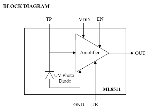
This IC (ML8511) outputs analog voltage proportional to the amount of UV light. Because it can output voltage, it can for example, directly connect to A/D converter mounted on MCU, and there is no need for a circuit to convert photo-electric current. Because it is a small and thin package, it is best used for mobile devices.
Specifications
Maximum sensitivity wavelength
365nm
Power voltage
2.7 to 3.6V
Consumption current
Typ. 300
I was going to make it small surface mount circuit board , this will just hold the chip with tracks coming out to the edge of the circuit board
with terminal connections,
my idea for this circuit board I was going to have a double sided board you would position the chip on one side of the board
and solder the holes on the other side this will draw to solder through to the surface mount chip
if this works it would be no problem for me to supply small board with the chip mounted
I have powered up the chip , everything looks good as soon as the hobby board
humidity Sensor arrives I will wire the unit where the humidity chip should be mounted
the recommended voltage is 3v need to add a resistor to drop-down voltage
and a 500 resistor on the output to bring it into the UV index scale
I soldered the wires on the back of the chip , using some very fine wire
Michael - that’s looking great - I have just revived the other thread ( 1-Wire Feature Request: UV Sensor using a single calibration value - WD Feature Suggestions) on UV using 1-Wire and separate component plus mini opamp board as in NZ we get a lot of skin damage to UVC and you can specify a broader - lower range device and have it in the std LED clear package to be externally mounted.
I have the data at home as have been discussing woth StokesValleyWeather, but both systems need the 1-Wire option to be switched into UV service inside WD and for the WD UV to accept the 1-Wire signal as a valid linear signal. I want to get the package that SVW is working with and an optimal photo-diode for our environment.
some information on specifications the uv max is 12.5
ELECTRO-OPTICAL CHARACTERISTICS
(VDD=+2.7 to +3.6V, Ta= 0 to +70C)
Parameter Symbol Min. Typ. Max. unit
Supply Current (active mode) * IDDA - 300 500 A
Supply Current (standby mode) * IDDS - 0.1 1 A
Wavelength of max. sensitivity p - 365 - nm
Output Voltage (Shading) * * Vref 0.95 1.0 1.05 V
Output Voltage (10mW/cm2 at p) ** VO 2.08 2.2 2.32 V
[color=red]UV-index / (VO
Looks like finding the ML8511 might be a problem in the USA. Mouser supposedly is a distributor, but a search of their site doesn’t show it and NU Horizons is also a distributor, but it looks like the minimum quantity is 24. I’ll keep looking as it looks like a great project.
I have seen the MS warn of UV 13.5 and it may even be 14 I think recently. We would need a range to 15 including UVC. I am not sure what the feasibile range is with the other project.
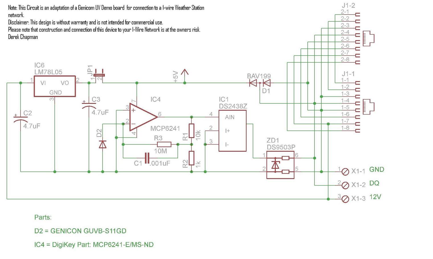
After a phone call from TokKiwi prompting me to post my design from an earlier posting, please find attached a diagram. I am not going to have time to further this project so the WD community can benefit if it works. This circuit is an adaptation of Genicom UV Solar demo board connecting directly to a 1-wire board. I have a circuit connected directly to an old JJWare Humidity board minus the Humidity sensor and a resistor. It seams to work well in the tests that I have done so far.
The only component I am unsure of is C1 as I have not been able to verify its, have tried to measure it and it is either .01uF or .001uf I think based on the Speck sheet of the Op Amp.
If the UV sensor specified is used, a linear output should result. If Brian can add the ability for WD to read the VAD value from a from a DS2438Z you should be able to get a WHO UV Index value. The Calibration value is then constant.
i.e. WHO UV Index = VAD / Xcal.
E.g. WHO UV Index of 5 = 0.65V / 0.13
With the Voltage output of the Circuit should not require individual Calibration Values/ranges for the index. Calculation to 1 Decimal place should be OK.
I guess if you have a high gain op-amp then the device and amp need to be close together so yes. But using a diode that is capable of either being in the weather or shrouded in a spherical polycarbonate clear shell as I have done recently with my solar sensor is my aim.
EricVic is still following these threads but said he can’t form an integrated board for a while yet but he is very interested in protypes that he might emulate, reading between the lines.
Yes, you can’t put that 10 megohm input at the end of any length wire. If you are aiming for a dome construction then I wish you luck, most plastics are pretty good UV blockers and polycarbonate is an especially good UV blocker
Yes I was concerned about the polycarbonate and other materials, and so was more insterested in the LED format, or the bare quartz one if the body is stainless steel.
The 10Mohm is part of a feedback circuit and does not represent the impedance across the diode.
The input impedance of the opamp itself is 1013 ohms, essentially infinite, the 10 meg ohm is also connected to that input and goes to ground via the 1 k ohm, so the input impedance of the circuit is pretty much determined by 10 meg ohm and its parallel capacitor.
There are many other opamps from e.g. TI that will do the job that are a lot easier to find than that microchip part.
I was going to check the performance of that chip against others and see what else there was as an equivalent or better and also analyse what is needed for other op-amps such TL series etc…
I was reading about plastics to house the uv chip I am experimenting , what I have read pure plexiglass will do the job nicely
I am waiting for a humidity sensor to connect the chip I’m experimenting with
I think this chip would work with the uv1 Oregon Scientific Wireless Model WMR928NX project will test this after I completed the tests for the 1 wire
the output is linear
14/02/2009
I have mounted the sensor inside a plastic housing, using a herb container , for the covering of the sensor I’ve used a glass from
a old damaged UV sensor ,
this will also house the hobby board humidity module ,which the uv sensor is going to be connected to